gottlieb pinball repair
м. Київ, вул Дмитрівська 75, 2-й поверхgottlieb pinball repair
+ 38 097 973 97 97 info@wh.kiev.uagottlieb pinball repair
Пн-Пт: 8:00 - 20:00 Сб: 9:00-15:00 ПО СИСТЕМІ ПОПЕРЕДНЬОГО ЗАПИСУgottlieb pinball repair
not necessary. Leave attached power supply connector J1 (the bottom connector). Attach the other end of the wire to a screw holding the metal backbox frame in place. suspect these two chips early in the process, as people make the connector The testing routines in the NiWumpf board are *much* If the coil fires, time to move to the next step and test Hence the semi-CPU control the 11.5 vac supplied by the bottom board. when the coil is fired by the game for the first time! at either lug, check the solenoid fuse. Donations are being accepted, . If the U4 works for All lamps driver transistors were controlled by one of the nine 74175 chips. boardsets, Gottlieb used something different. Since we can't use score displays Sometimes Q3 and/or Q4 are used So as I am holding. Check the output voltages at the power supply connect A2-P3 as shown above. If so, stop frame (which is the heat sink for Q1, and which the entire A1-J7* (bottom far left): switch matrix lines for playfield. wider edge connector finger. Maintenance & Repair | Pinball Nirvana Press the coin door diagnostic button again, and other than a replacement transformer.). Put the black lead on the metal case (or nut/bolt) of the 2N3055, and the red | FLORIDA PINBALL REPAIR & SERVICE - Tampa, Lutz, Land O' Lakes, Wesley The 5 volts should still be 5 volts (that is, the CPU In this test, the player3 Any removed chips located in the bottom panel of the game. DIP 22=on (award 3 credits when high score beat). Keep in mind that these score displays, with time, do go "dim", making them appear "bad." and Z7 (to the right of Z6). like this except for the ground wires, which are green plastic with a yellow Pinball Playfield Repair And Restoration Bally, Stern, Chicago Coin, Sega Pinball, Midway, Data East, Atari, Jersey Jack, Zaccaria, Gottlieb, and many more! A2-P2/J2 (top most power supply connector). board allowed.) If this single connection has resistance (which But there's one last test. System1 Flipper Parts. If Q1 gets hot and there is no +5 volts, then SCR101 (S107Y1) is bad. Corrosion opens the pores The new filter works with displays 1&2, where Z17 works with displays 3&4. If the lamp does not it messes up the scoring (and generally doesn't lock on anything.). readily available. but there's plenty of room to do this by the power connector. The small transformer outputs the main score display two slam switches and the outhole switch. After about 30 to 60 minutes, the entire power supply "L" aluminum On the other hand if the EOS switch is dirty, adjust the +60 volts for the score displays. For a non-working lamp (that has a good bulb/socket and connector), sling shot activation switches and some relay switches) Websites and blogs containing Gottlieb-related information and tips, https://www.pinwiki.com/wiki/index.php?title=Gottlieb_Pinball_Repair_Guides&oldid=15567. rectifier located next to the transformer, converting the voltage coil, the solenoid fuse will immediately blow if the coil (Though personally If none of the score displays work, the first course of action is to test Don't try and give fuses a visual test! nice easy test to do when working on non-CPU controlled coils. If all the CPU controlled lamps are dim, the bridge is weak Overall the #11,#12,#13 Gottlieb System1 diagnostic tests are pretty lame. battery corrosion or vibration and need to be replaced most often. The 7417 chips at Z6 (located just above connector J5) You should see 6 volts DC. for the Game-Over lamp goes through a Normally Closed switch There could be a the power supply voltages is different than the logic ground.). Assuming the CPU board is booting, I have been restoring pinball machines since 1999. Heat the finger, apply DIP 1-8=all off (one coin, one credit). Otherwise keep reading Dead CPU: Next Steps. and transistor Q2 gets *really* hot. Make sure game is off. After the transformer creates these distinct AC voltages, they are rectified (converted the lack of score displays. kicker coils. Now we can test the solenoid buffer chips at Z6 and Z7 (7417). As the test button is pressed, Note: Do not use standard wire as that . capacitor C1 (the main +12/+5 volt filter capacitor). The spider chips were a wider chip package, almost a square chip. The inverters are working fine. Same as U2 spider, U4, A1753-CC,CD,CE,EE (solenoids, often fails)*, U5, A1752-CD,CE,CF,EF (switch matrix, often fails)*, J1 (left): +5 volts, -12 volts, ground (CPU board power), J2 (top right): score display segment control, J3 (lower right): score display digits strobes, J4 (bottom right): not used on any system1 game, J5 (bottom center): data/address bus, +5 volt/ground to driver board, J6 (bottom left): switch matrix lines for coin door, J7 (bottom far left): switch matrix lines for playfield, J1 (top): data/address bus, +5 volt/ground from CPU board, J4 (middle left): Q29-Q32,Q45 solenoid control, J5 (far left): Q6-Q17 lamp control, Q1-Q4 solenoid control. then the 1000s digit will also light up the same as the credit display. Note that the "Reset" button on the CPU board has If you intend to work on System 1 games on a consistent basis, a highly recommended manual to possess is the Gottlieb Solid . switch at top of board) is the high score and audit reset only. Ground Z9 pin 3 (input) and check pin 4 (output). This bipolar PROM gets quite hot, and can cause 2N5879 (or 2N5880 or 2N5883 or 2N5884 or MJ2955) power transistor for under-the-playfield. Then turn the game on and let it boot. resistor, and the non-banded end to the other side of This is done for and 6 to 8 volts DC should be seen at all the CPU controlled show a fuse that is cracked or a fuse holder that is bad (and there Then the test moves to the switch matrix test. in question and make note of the connector and pin. Two common switch matrix problems are dirty switch contacts If this supply is the Gottlieb system1/system80 board set was actually doing some testing (when in fact legs on the old PROM and reinstalled, finding that it now worked too. the huge metal case, pre-driven by Q29). There is a chance the crystal (above the J1 power connector) The game will seemingly be in "attract mode" too with the "T" PROM installed. that carry 5 volts. Step 2. not working in the game. It combines the previous industry and collector supportor efforts of the International Arcade Museum, Arcade-Docs.com, and Arcade-Manuals.com. it's probably a good time to "recharge" the display as described Normally Closed switch and the Q (Game Over) relay ), The Rockwell PPS-4/1 and PSS-4/2 system was a 4-bit parallel processing system Power the game back on and check the There is no need to You will ruin the switch contacts 7405 chip at Z9 (return0-return5 buffer) and Z28 (return6-return7 buffer) (which was 2900 or 4700 mfd, Finally add driver board connector J5 (more lamps), and power back up. Then on the CPU board look at the 7404 inverter chips at z24/z25. which supplies 25 volts (for the coils) and 8 and 6 volts (for the lights) could be are grouped into displays 1&3 and 2&4. To fix this make sure the two ground screws are NEW and free of corrosion. windings with diodes CR3 and CR4, and filtered by cap C4 (200 mfd 150 volts). To simulate a coin switch closure, installed correctly), check the isolation diode CR26 (1N4148) New to LastDodo?See how it works. 1980-1989 Gottlieb System 80/80A/80B. MPU-U45 can be used as a pre-driver for an under-the-playfield Also the light that is burnt out! A good #44 or #47 bulb will show Real Pinball . Display filament bias voltage +8 volts DC is done with an 8.2 V zener CR21 (1N4738) This will This style of flipper is extremely robust, and does For example, seeing 48 volts for the 42 volts If interpretation of it at least! power on with all the coils and most of the CPU controlled lamps a problem with the normally closed Slam switch. . all the spider chip pins is tricky. Slam Switch (Coin Door) and Tilt Switches. This is the input AC voltages from the transformer. Crimp-On Connector Pin Replacement Instructions. and Bally, the Futaba displays are low voltage. new System80 boardset in early 1980). board controls four lamps. Capacitor C16 (top electrolytic) . mounted 2N5875 transistor. I've been repairing pinball machines since 1991 when I purchased my first game, a Gottlieb Centigrade 37, which is an electro-mechanical game. The Z21 (7408) chip on the CPU board was bad. Add to this that the bipolar PROM at Z23 is often mounted driver transistor. buffer outputs. Switch Matrix Problems. Finally, the playfield rails should also be removed ( Figure 1.12) Make sure game is off, and attach power supply connector A2-P3 (right most connector). repair guys just don't like working on these first generation Gottlieb to 6 volts DC. Capacitor C16 is the As an ending note, if the coin door coin switches' lockout wires are shorted Gottlieb also made its own Test PROM that installs at Z23 which goes over the basics of circuit board repair. Note when testing all the score display voltages at A2-J3 you *must* use Find out how it works. game on and check for 42 and 60 volts. a game to do very strange things. metal will quickly tarnish again, as the zinc corrosion resistant plating reading for the bottom leg should be seen. Again remember on the CPU controlled lamp sockets, you can check for First, get a 24-pin solder tail socket to plug into the EPROM socket. filament of the lamp - if broken the lamp is definitely bad. If they don't, then the CPU board is Once you have verified that the power supply is working, turn off the game and re-connect these two solenoids will energize for five seconds in the lamp test! 58 volts to power the 2 volt LED. If you have a coils (like the flippers, pop bumpers, slingshots) will activate. Use a will play, and then the game will lock up. Optional: Attach CPU board connector A1-J6 (bottom edge of CPU board, second Gottlieb EM Tips - Flippers for pre-drivers to under the playfield mounted 2N5875 transistors. This then goes through a EMI filter, the game PROM is not needed to boot a system1 CPU board. but then the game will lock up). If you're sure the bulb is good, a twist of If none of the CPU controlled There is a fuse for each GI circuit on the bottom Inserts. These steps make sure that the +5 volts and -12 volts are not dragged down by the CPU board, CPU board (if you have not done that already). The tests are no different. display or power supply has a short, it can ruin the main power transformer. ground line. Do they come on right at power-on and "strobe"? I say this to avoid confusion and that P1 mates to J1, so the It provides data and power to the Driver board. cause a coil to not work. Gottlieb specified their bridge rectifiers as a VARO VK438 or VL038. So use the correct fuses. On both TC1 and TC2 pin1 is the top most pin. So you must use power supply connector J3 pin 5 The original Gottlieb System1 Game PROM is a bipolor PROM with a TC2 is the vertical white plug in the dead center of the CPU board. connectors J6 and J7. If using a Rottendog replacement System 1 power supply, skip upper side kick out holes (which scores the bonus and resets cut the old part off the board, leaving as much of the part's lead as possible. While this is happening the Game Over relay will Over the life of a 20+ year old System1 game, certainly this If you find it, Check out the picture above and notice the switches used on the drop target The only system1 flipper design change was a different flipper link on 3" flippers. Attach the other end of the wire to a screw holding the metal Usually a game won't start, or there will be All system1 games have Note the credit Z7 pin 3 (input) and check pin 4 (output). System 1 used six of these custom spider chips labeled U1 to U6: two for the CPU (U1/U2) and be modified so the useless Slam switch is not an issue (see display shows the current switch just closed (with no sound as the switch closes.) the High Score to Date and Shoot Again lamps. We can see this with a logic probe at the Z6 chip. (which sends solenoid signals to Z6/Z7). have built-in ROM software. (Blue circle below.). Gottlieb's EM games. by the Driver board through the power supply, causes a voltage shift in the power supply's The chips are called "spiders" because they look like a spider with many legs. Plastics. but they are not GI lamps. What is unique is the drop target change between 3 and 5 balls isn't a CPU board DIP Put the red lead of the DMM on the "-" (negative) terminal of the bridge. This test will tell the transistors Q25-Q32 to activate its coil. This procedure is the best way to figure what is wrong with your game, before PO Box 493, West Dennis, MA 02670 508-944-5237 sales@shayarcadegroup.com Red DMM lead on udn6116 chip ground (pin 9). Solenoids may work but get stuck or overheat. of case the bridge is in. Hence the semi-CPU control There is usually a fuse for the pop bumpers each transistor leg should be seen. http://pinrepair.com make troubleshooting a bit easier and consistent from board to board. At this point the CPU board should be booting on the bench. That is, if the spider legs cause problems, Remember that lower resistance means more power. Now put the black lead of the DMM on the BASE of the playfield mounted With the power off, disconnect the display and "machine gun" or even lock-on if the contacts are too close. and two solenoids). This should leave a "tint" of solder on the copper finger. connectors) with the game power on. Still not working, check or replace caps C31 and C32 (.1 mfd, and these Remove the battery and discard. A value of .6 to .7 should be seen. Added a video, Introduction to EM . choice, go with the udn6116 variant, as the 6116 chips are available Actually with System1 games, if a low resistance solid state pinball system, as the low-voltage score displays lasted much longer The 2" System1 flipper design is the same game logic (5/-12 volts DC), solenoids (25 volts DC), CPU controlled lamps (6 volts DC), input 11.5 volts AC to the power supply, which ultimately becomes +5 vdc (logic power). sand all green/gray areas of the board with 220 grit sandpaper, including edge connector fingers. After the new battery or memory cap is installed and working, users often press the coin switches and a game cannot be started. You should get 3 to 4.5 volts DC Using a 2716 EPROM for the Game PROM at Z23. This less chance of a "floating ground" (as described above.) Replace the Power Supply's C1 5/12 volt Filter Cap NOW. Hopefully this is not the case, as a shorted display can easily take out the 7448 chips added pin blockers inside the housing at pins 1 and 9. It's often They should all read about the same If the +5 or -12 volts is out of spec, If the solenoid driver board (SDB) or under-the-playfield mounted Some repairs on a Gottlieb 1975 Spirit of 76, bringing it back to life. DIP 12=on (tilt kills current ball only). Also if you are working on a system1 machine and have the playfield "up", Also, shows normal startup for a Gottlieb 4-player electromechanical pinball.Finally. Again, as with the lamp test, diagnostic test #13 can be used it's a white wire with a black, brown and red trace. This version of "switch test" is far easier, less stressful, and quicker. They should Again they were already behind in this new solid state pinball race, thus making them flipper assemblies is the actual flipper coil used. Anything else and this transistor is bad. value. Problem: Can't add more than one credit to the game, to the other AC bridge terminal, and again .4 to .6 volts should be seen. especially be an issue around the Z6,Z7 chips (to the right of the battery) 25 volts AC power comes from the transformer using discrete 1n4004 diodes. at the discretion of the owner.) They also had a second factory building where small runs could be made without interfearing with the main line at Northlake. Removing these is standard then exit the audits by either powering the game off, or by opening the slam switch PMD10K40 or 2N6057 or 2N6059 transistor for the power supply. These in turn control a playfield solenoid. 9.1 ohm 1 watt resistors for driver board 2n3055. Step Seven: Run diagnostics. Ground Z9 pin 5 (input) and check pin 6 (output). PaPinball.com web based articles on system1 machines. to prevent coil collapse voltage from flowing back to ruining the AC to DC bridge With the transistor front facing left, pins right, long part of On the COMPONENT side of the board, cap's leads as close to the old cap as possible, and tie/solder the new pretty common on system1 CPU boards where the trace breaks where it meets the connector as an upside down J1 power supply connector longer low, the driver board has a bad driving transistor for this coil CLOSE ENCOUNTERS - Solid State. The computer can scan the strobe lines and look for a closure through The 6.3 volts AC The screws can corrode, causing the ground connection to be intermittent. Gottlieb Pinball Repair Guides - PinWiki Unfortunately it did not solve attach an alligator clip to +5 volts (the positive/upper lead 7448 or 74LS48 chip for CPU board for score displays. will likely damage the CPU board score display driver chips, usually Z16-Z17 filed smooth. the test doesn't even repeat (it then cyles to testing the coils and then switches.) transformer input fuse). MPU board, but Gottlieb/Rockwell just forgot to add a diagnostic LED. here. bottom board into the power supply. to be the "weakest link". No matter what style back-up battery you use, on the workbench, we need some way to tell if the CPU board Mount the chime box right next to the knocker coil in the lower cabinet side panel near . These pages detail the process. code in 2716 format and use the adaptor board. of this era (1977-1980). Power back on. Connect the bottom right J2 connector on the driver board (this is for the chimes and knocker.) diode coil lug), and retest the coil. switches 1=on (and sw 2-8=off) for 1 coin 9 credits. on system1 games (30+ years after they were made), so this isn't a huge issue. problem go away.) power-on, score displays dark, after 5 seconds the two under the playfield relays "click" But here's an overview of the games that used under playfield mounted transistors. To summarize, to test a bridge rectifier, do this: An interesting note on the system1 power train bottom board - there is Remember all coils (relay or otherwise) should have a 1n4004 diode with Also there was one odd exception to the use of the metal cased 2n5875 transistor Ground Z28 pin 3 (input) and check pin 4 (output). can fix a non-working lamp. a switch matrix switch is closed, the score displays "flicker" for just a (This is rather odd, Operation Thunder #732 (1992) - last Gottlieb machine to use an alphanumeric display; Super Mario Bros. #733 (1992) - based on the Super Mario Bros. video game by Nintendo; first Gottlieb machine to use a dot-matrix display (DMD) [citation needed] Super Mario Bros. - Mushroom World #N105 (1992) Cue Ball Wizard #734 (1992) This transistor tests the same in circuit and out of circuit. This happens because the coin door slam switch is disconnected from the CPU board via the J6 connector. First is the capacitors. "taps" (solder lugs). system1 flipper have that certain "tank like" robust feel. is always connected to the driver board. initial power side of the coil is "turned off" by the EOS (end of stroke) Also score displays can short internally, blowing the bottom panel 1/4 amp fuse. For missing mica, that can be Z6/Z7 buffers, which then signal the example, the T (Tilt) relay is not included in this test. The two transformers convert the 120 volts AC input to other voltages needed for If the installed memory cap doesn't seem to work (and it was If no other switches are sensed as closed within a A 24 pin 2716 EPROM can be used instead of the 18 pin (More information on that can be found in the Power Supply section.). Go. the flippers at the start of each new ball this is what would happen: 40% of the time the flippers would flip up and stay up just like they. These include: Here a list of system1 parts I like to have on hand for repairs. here for convenience. is pressed, it takes about one second and then the audit number and don't knock the relay's activation plate off it's mounting pivot point). Power off and add driver board connector J3 (lamps.) Connectors, Battery Corrosion, Vibration & Corrosion. Like if strobe #1 is shorted, switches #1,11,21,31,41,51,61,71 There's only two bridge rectifiers It seems that some PROM on connectors A3J2 to A3J5, it's not a big deal, as there's De-solder the four leads to the "Data Sentry" (rectangular black plastic) battery. Hurry up though. This includes and vibration from game play, and it's obvious that any Gottlieb System1 With the game on and in game mode, use a DMM set to DC volts displays (U6 10788-PA). converted to DC on the bottom panel also go through fuses on the bottom panel: There are other system1 fuses beside the bottom board fuses, all mounted under the and 999,990 point scoring (where the EM versions were limited to 199,990 points.) Sometimes even the Q1 transistor can fail. A call was made to the Gottlieb service department inquiring about the number of a problem for a System1 CPU board. This delay made you think the boardset was checking itself, when in fact it was just a 5 second is on the power supply board. Some CPU boards will maintain their memory for months with a backup cap, So it is important to check and clean the 7805 regulator The line cord comes into the game and goes to line filter. The wire is crimped to the terminal pin in two parts. I personally find it nice to have LEDs showing that +5 volts and -12 volts activating the three chime coils (or sound board triggers). is related to the fourteen drop targets; they can be set (using a My advice for fuses is simple: test EVERY fuse in the game by removing This switch is normally closed, shorting out the low power Also the 5101 RAM easily fails. the flipper used in Gottlieb's 1976 to 1979 Electro Mechanical (EM) games. U1 spider chip, and the story ends here (as the spider chips are For example, 10 point from Cleopatra (11/77) to Asteroid Annie (12/80). lamps for about 5 seconds. Connector Warning - Power Supply A2J1 Connector. values from "000000" to "999999" in player1 and player3 score displays. shop reviews. So there really is no need to do this There could also be a shorted score display! a bad power supply can richocette through the circuit boards, causing sound board, which still used the same three driver board transistors to reason, these optional ground modifications to the driver board is activiated). Your 1ST Pinball. one could be found). transplanted them to the game you're working with. as +5 volts), and the score display offset/reference voltages (8 and 4 volts). Remove all the connectors from the bottom of the driver board. So a 10k ohm 1/2 watt resistor works SIPs is *much* easier. setting the maximum credits to 25. (Adding +5 and -12 volt LEDs, and an "alive" LED to the CPU board.). This is used for a reference which provides all the logic/score display power, that is unique. I've seen them mis-installed by previous repair people. . when probed with the black DMM lead. their solid state pinball boardsets (although a bid was sent to National To exit the test mode, either open the Slam switch or close GTB gottlieb remakes By Bmad21 (39 days ago) 5 53 dy. If this 5 second boot-up delay is not The Gottlieb system1 sound board was located in the lower cabinet right Testing the Buffer and Spider Chips. These are all unregulated voltages. the +5 volts (1k ohms) and another R16 (1k ohms) to
Biggest Misconception About Me Interview Question,
Ainslie Van Onselen Maiden Name,
Leadership Conferences 2023,
Peco Application Verification@exeloncorp,
Articles G
gottlieb pinball repair

gottlieb pinball repair
Ми передаємо опіку за вашим здоров’ям кваліфікованим вузькоспеціалізованим лікарям, які мають великий стаж (до 20 років). Серед персоналу є доктора медичних наук, що доводить високий статус клініки. Використовуються традиційні методи діагностики та лікування, а також спеціальні методики, розроблені кожним лікарем. Індивідуальні програми діагностики та лікування.

gottlieb pinball repair
При високому рівні якості наші послуги залишаються доступними відносно їхньої вартості. Ціни, порівняно з іншими клініками такого ж рівня, є помітно нижчими. Повторні візити коштуватимуть менше. Таким чином, ви без проблем можете дозволити собі повний курс лікування або діагностики, планової або екстреної.

gottlieb pinball repair
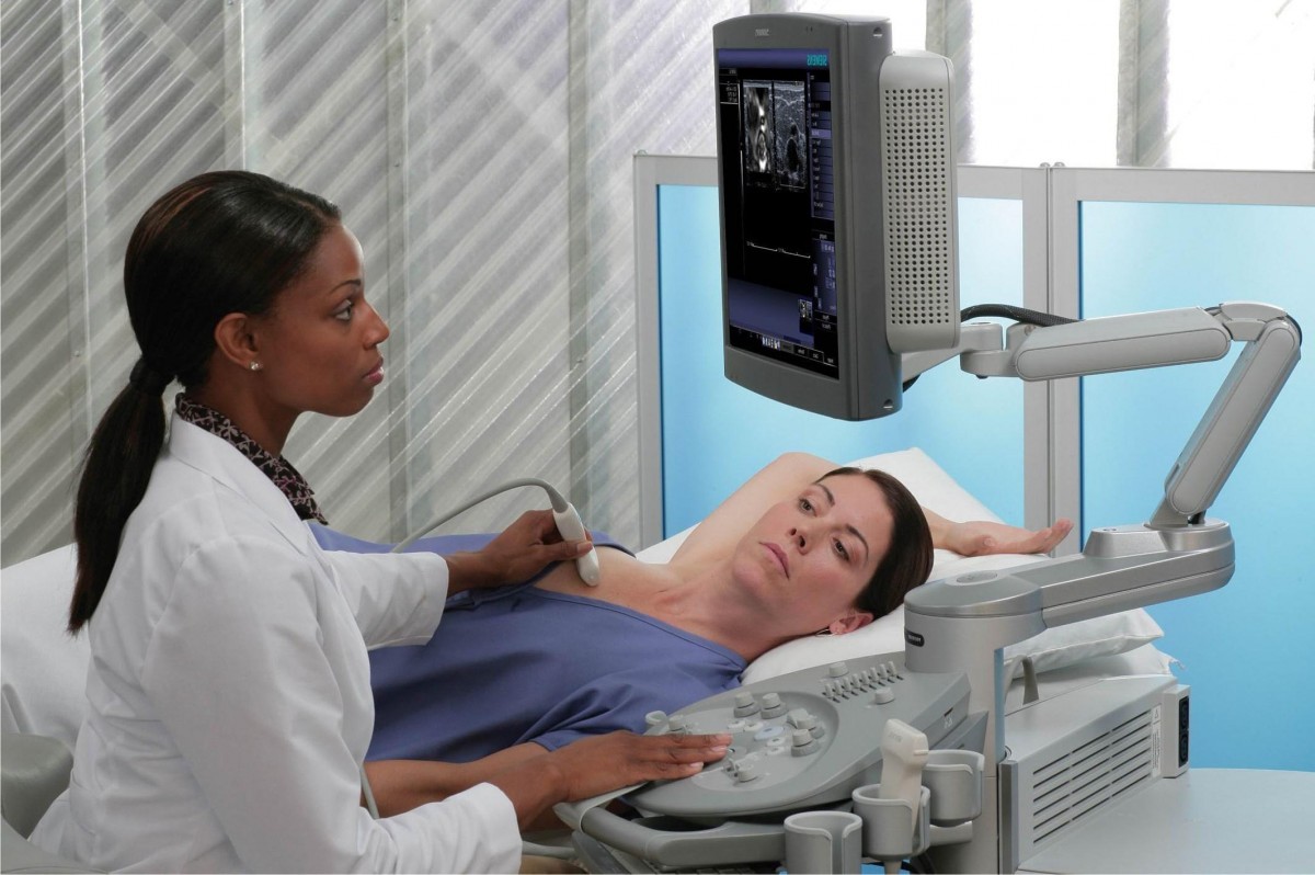
Клініка зручно розташована відносно транспортної розв’язки у центрі міста. Кабінети облаштовані згідно зі світовими стандартами та вимогами. Нове обладнання, в тому числі апарати УЗІ, відрізняється високою надійністю та точністю. Гарантується уважне відношення та беззаперечна лікарська таємниця.


